Page 1 of 1
CHEVROLET ISUZU NHR REWARD 2022 Euro IV - Engine 4JH1-TCN_Variable Geometry Turbocharger & Intercooler - 2999 cc Diesel
Posted: Tue Apr 22, 2025 8:04 pm
by BrayanArangoG
Engine works Good
Forum moderators please converting the signals from the ".psdata" format to the ".mwf" format.
Thank you.
Re: CHEVROLET ISUZU NHR REWARD 2022 Euro IV - Engine 4JH1-TCN_Variable Geometry Turbocharger & Intercooler - 2999 cc Die
Posted: Thu Apr 24, 2025 5:17 pm
by admin
Hello,
Converted files are attached:
Re: CHEVROLET ISUZU NHR REWARD 2022 Euro IV - Engine 4JH1-TCN_Variable Geometry Turbocharger & Intercooler - 2999 cc Die
Posted: Wed May 14, 2025 2:16 am
by BrayanArangoG
Dear administrators, I would greatly appreciate your assistance in executing the .mwf files you used to replicate my post regarding the pressure measurements of the 4JH1-TCN diesel engine, taken with the WPS500X pressure transducer.
When attempting to run the script in the USB OSCILLOSCOPE software, I receive the following error message: "Failure in analyzing the cylinder pressure curve (possibly the type of pressure sensor was incorrectly specified, or the sensor or its connection is defective)". To resolve this, I tested all available options in the software for the .mwf files:
1. Pressure sensor channel: I always selected channel 1, as the pressure was recorded using a voltage range from 0 to 5 volts.
2. Pressure sensor type: I tried the options: Px|Px8, Px|Px8+Flex, Px|Px8+Extension, Px35, Px35+Flex, Px35+Extension, but none worked. The error message persisted with every attempt.
3. Synchronization sensor channel: I selected "No", as only pressure measurements were made on channel A (1), without a synchronization channel. Is it correct to assume this?
4. Valve synchronization type: I tried the options: Otto cycle (DOHC/SOHC/OHC/OHV), Otto cycle + VVT/Vanos, Miller/Atkinson cycle (Toyota Prius/Mazda SKYACTIV), VVL (Valvetronic/VVEL/Valvematic...), but again it didn't work.
In summary, I tried all possible combinations with the available options in the USB OSCILLOSCOPE software, seeking to specify the pressure sensor type correctly. However, I did not find an option to select the WPS500X pressure transducer in the "Pressure sensor type" menu.
Additionally, I noticed that the available "Valve synchronization type" options seem to be geared toward gasoline engines, while my tests were conducted on a diesel engine (4JH1-TCN). This leads me to believe that it could be a cause of the issue, as the pressures in a diesel engine (MEC) are higher than in an Otto cycle engine (MEP), and the software may be interpreting this as a sensor error.
To rule out this issue, I repeated the pressure measurements on the 4JH1-TCN diesel engine and upload the .psdata files in a new post for conversion to the .mwf format.
I greatly appreciate your time and any guidance you can offer to help me correctly execute the script in the USB OSCILLOSCOPE software with the measurements taken from the 4JH1-TCN diesel engine.
Kind regards from Medellín, Colombia,
Sincerely,
Brayan Arango González — Mechanical Engineering Student, UdeA
Re: CHEVROLET ISUZU NHR REWARD 2022 Euro IV - Engine 4JH1-TCN_Variable Geometry Turbocharger & Intercooler - 2999 cc Die
Posted: Thu May 15, 2025 9:52 pm
by admin
Hello
For working with diesel engines, we recommend using the Psg200 sensor, which is designed to measure the pressure graph in a diesel engine within the range of 0 to +200 Bar.
https://usbautoscope.eu/products/psg200 ... ransducer/
Pressure transducers Px, Px8 and Px35 are designed for measurements in gasoline engines only.
For synchronization we recommend to use low amps current clamps that measure the control current of the fuel injector of the cylinder being tested.
Here is an example of graph of the pressure in the diesel cylinder obtained using USB Autoscope IV automotive oscilloscope and PSG200 diesel pressure transducer:
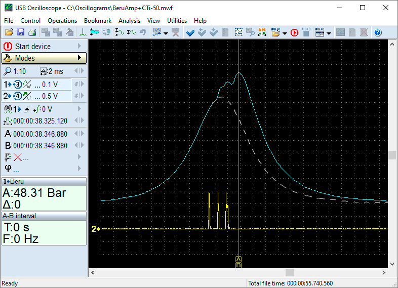
- USB_Autoscope_IV_PSG200.png (40.2 KiB) Viewed 6006 times
The blue trace is the pressure graph in this cylinder.
The yellow trace is the control current of the fuel injector of the cylinder being tested.
The dashed white line shows what the pressure graph would look like if no fuel was supplied to the cylinder.
Here is an example of your graph of the pressure:
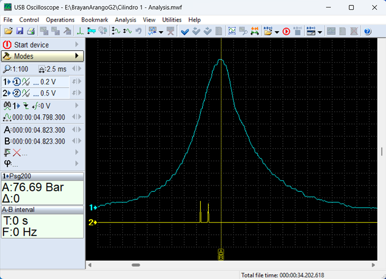
- Cilindro-1-Analysis.png (203.73 KiB) Viewed 6006 times
It looks like the pneumatic channel is incorrect, and the graph itself has incomprehensible distortions.
You can read the document about Px script designed to analyze in-cylinder pressure waveforms, providing insights into gasoline engines diagnostics using pressure transducer:
https://usbautoscope.eu/library/px-script-manual/